

Ensure all permits, safety plans and approvals have been obtained. Any research undertaken within Australian Marine Parks (AMPs) requires a research permit issued from Parks Australia. Refer to AusSeabed’s permit guide for further useful information: www.ausseabed.gov.au/resources/permit.
Define question/aim of project. This may be done in conjunction with local communities including Traditional Owners. See Indigenous Leadership and Collaboration in Chapter 1 for further details.
Confirm sampling design is statistically sound with adequate spatial coverage and replication, and addresses the initial question/aim. This is generally achieved through the use of an explicit randomization procedure to ensure that independent replicates are obtained (Foster et al. 2017; Smith et al. 2017). See Chapter 2 for further details on sampling design.
Select appropriate transect design for AUV deployment. Two AUV transect designs are recommended for marine monitoring: 1) broad grids and 2) dense grids. Foster et al. (2014) evaluated a number of broad grid designs and determined that a grid consisting of three long parallel transects, with each transect separated by ~150-200 m (each generally covering a total of 2000-4000 m) was generally the most optimal design for monitoring purposes (Figure 4.2). The dense grid transects are used to get a complete coverage photomosaic that covers a 25 x 25 m scale (Figure 4.2). Combinations of both within a survey can be applied if required (e.g. Morris et al. 2016). Essentially, broad grids cover more ground but are less repeatable, whereas dense grids are more repeatable but less general (essentially you get more information about less).
The decision to which transect design is most appropriate is driven by the question being addressed, as well as the environment, available time and logistics of AUV deployment and retrieval. For example, in the deeper regions (> 100m) within the AMPs that are exposed to strong currents, dense grids are not recommended for temporal monitoring purposes because the challenges with maintaining physical position in these conditions make it difficult to successfully repeat the same 25 x 25 m grid. This ultimately results in limited temporal overlap between sampling points over time (Figure 4.3). Where inference is the primary objective of the study it is recommended that broad grids are used to increase sampling power (Chapter 2). Conversely, if the physical structure of the seafloor or biota (e.g. corals; Ferrari et al. 2016a) are the focus then dense grids are best suited.
Broad grids are generally used in mid-outer continental shelf Tasmanian waters as a result of strong currents. Conversely in Western Australia, the patchy nature of inshore reefs, coupled with a lack of shelf slope to encompass a wide depth range along broad grid designs meant that dense grids surveys undertaken within each of a replicate number of patch reef systems and depths was the most pragmatic solution. In southern Queensland, dense grids were the primary method used due to the initial process-based research focus, however, the missions are time intensive, as is post processing and analysis, and could readily be modified to a broad grid design in the future to simplify analysis. In NSW a combination of both broad and dense grids has been conducted at most sites over several time periods, although more recent surveys in the Sydney region have just used broad grids.
Stereo-cameras must be pre- or post-calibrated in shallow water using the techniques similar to those outlined in Boutros et al. (2015).
Decide on appropriate navigational systems (e.g. USBL). Accurately geo-referenced imagery is crucial to the success of any AUV deployment, and appropriate effort must be given to this during the survey planning phase.
Ensure appropriate software is installed on onboard laptops (e.g. AUV navigation software platform, GIS, etc), and potential users are familiar with it so that the AUV can be tracked and its mission success monitored while underway.
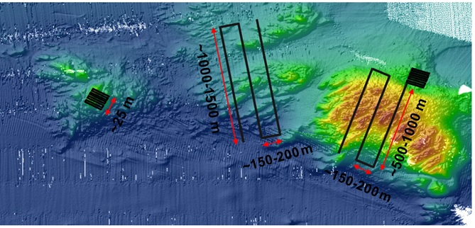
Figure 4.2: Examples of AUV transect designs over multibeam mapped reef features. Left: stand-alone 25 x 25 m dense grid transect. Middle: stand-alone broad grid. Right: combination of broad grid with a dense grid embedded. Note with this design broad grid transects are usually shorter due to the time required to complete both grid types.
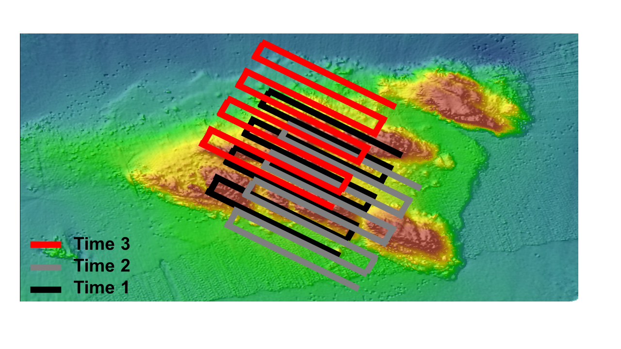 Figure 4.3: Example of spatial mismatch between sample time points for a 25x25 m grid in a high current/wave action environment. Note the limited overlap between all three sampling points.